K4HV
160M Collins 20V-3 Transmitter

Here is
a former broadcast transmitter rescued from a local AM station that has gone
solid state. This Collins 20V-3 project took a couple of years to get started. It
was in good shape. All paint is original. The iron was OK.
But…
The
entire metering board was kaput. The meter face white background was peeling
and flaking. Worse yet, the indicator pointers were corroded to the point of
disintegration. It was like salt water was sprayed in there and left. They
would not read correctly or even function. One needle blew right off while I
was trying to clean the meter! The
original company that manufactured the meters for Collins is no long in
business. After agonizing over Triplett and Simpson Electric catalogs for
replacements, I settled on a 4.5” Wide-Vue style with
the Simpson bezels. These meters are very common, the only difference being
they use a spade pointer. The bezels are black versus the original white/cream
colored bezels. They looked really good after a trial fit, so I left the color
black. They look pretty sharp. The official Simpson lighting kit is going to be
installed eventually. Side Note: The Harris-Gates BC-1H transmitter also uses
the Simpson Wide-Vue meters. By a stroke of luck the
Gates has a RF Ammeter with an internal thermocouple. It looks like it will
match perfectly. I found one on ebay from a Gates
that was being parted out and have it installed.
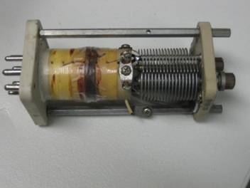
Here’s
one of the driver coils modified for 160m. One of the turns has been completely
removed and 10 turns were removed from the remaining coil. It dips very sharp
on 160m. I was thinking about rewinding the coil completely with enameled wire
but it works. For 160m about 40 turns are needed to get the assembly to
resonate. I built a mockup with a piece of PVC tubing and a variable capacitor
I had in the junk box to test it out first.
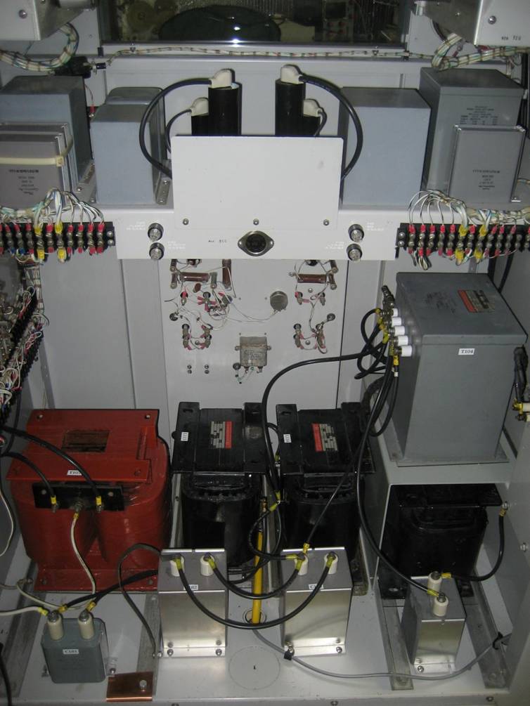
Here’s the LV power supply section and the iron. Solid
state rectifiers are used throughout the transmitter. I didn’t bother trying to
re-install the mercury vapor rectifiers. Nearly all of the HV wiring had to be
replaced. GTO-15 neon sign wire was used as per the original design. While all
the iron was removed, the transmitter was washed and dried. Simple Green in a
garden sprayer was used to clean out all the nasty stuff from years gone by.
The iron and oil capacitors were labeled to help reconnect everything. The fan
motor on the rear door was replaced. An exact motor replacement was found at
Grainger.
Tank Compartment set up for 160m. An MFJ 259B analyzer
was used to set up the Pi-L network. There are more than a few conversion
articles out there, but I don’t follow blind instructions very well. I wanted
to prove everything worked perfectly prior to firing the transmitter up.

I didn’t do anything weird or unorthodox but wanted to
keep the transmitter as usable as possible while maintaining originality.
Crystals for 1885 kHz and 1936 kHz were installed. Switching
from one frequency to the other entails tweaking the driver caps slightly and
adjusting the tank load/tune. I do have a hidden modification that I use
the unused pins on a crystal socket and inject a signal from an HP 8640B signal
generator. I modified an old Motorola crystal can with a BNC connector for the
“VFO” input. I wanted to “dual band” this transmitter on 160/75m, but after
evaluation it turned out more work than what it was worth. A lot of stuff would
have been ripped out.

Here’s the current 160m AM operating station until I
get the transmitter remote controlled from the main shack to the garage.
A Symetrix 528 drives the
audio. The Tektronix 7000 series scope watches the modulation peaks. The R-390A
does nicely for vintage AM listening.

Rock n Roll!


![]()